We need to pin down the size of a stationary air compressor by mapping your actual usage: list tools, note peak CFM and burst demands, and weigh how a larger tank or higher PSI affects delivery and startup cycles. Our approach blends duty cycle, line losses, and future needs to avoid under- or over-sizing. There’s a practical path forward, but the details that follow will determine whether your setup truly holds steady under load or requires adjustment.
Key Takeaways
- Map actual tool demand and bursts to determine target CFM at the planned system pressure, plus a safety buffer.
- Size storage (tank) to smooth delivery and handle startup surges, balancing cycle stability with space and cost.
- Assess peak simultaneous tool use and duty cycles to prevent undersizing and avoid energy waste from oversizing.
- Consider pressure drop, piping, fittings, and regulator losses to ensure the selected compressor maintains 100% load without starvation.
- Validate with a practical sizing checklist: measure usage over shifts, match to compressor displacement, and plan for future expansion.
Start Here: How Big a Stationary Compressor Do You Actually Need?
Determining the correct size for a stationary air compressor starts with a clear view of your actual use cases. We approach this by mapping demand patterns, duty cycles, and peak bursts across tools and processes. We’ll quantify continuous versus intermittent needs, then translate that into nominal CFM requirements at the system’s operating pressure. Our goal is to prevent oversizing that drains energy and undersizing that throttles performance. We emphasize reliability, maintenance intervals, and startup inrush considerations to avoid nuisance trips. Two Word, Subtopic unrelated, Two Word. By cataloging tools, attachments, and simultaneous demands, we identify a baseline. Then we compare compressor types, storage strategies, and pressure bands to meet those needs efficiently. We invite you to share your current workload to refine the sizing model precisely.
Understand CFM, PSI, and the Tank’s Real Role
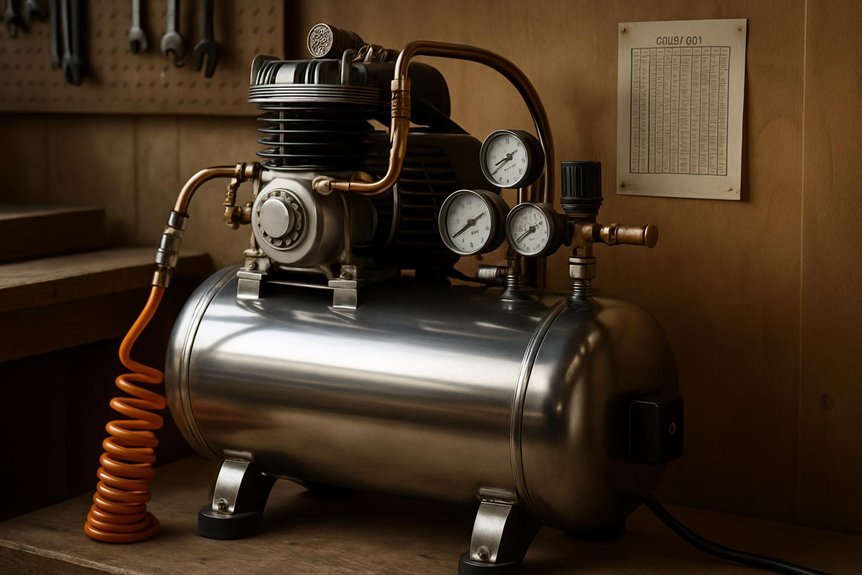
We’ll clarify how CFM and PSI define your real air supply needs, not just what the gauges show. We’ll examine how the tank’s capacity shapes startup stability, tool bursts, and continuous duty, separating storage from delivery. In short, the tank directly affects how consistently your compressor can meet demand at the CFM and PSI levels you target.
CFM and PSI Roles
How do CFM, PSI, and the tank come together in a compressor’s performance? We approach this by clarifying each metric and its interaction. CFM measures usable air volume at a given pressure, while PSI reflects the pressure the system maintains under load. The tank stores compressed air, shaping delivery by smoothing peaks and sustaining flow between cycles. In practice, higher CFM demands more flow than a fixed tank can provide at a given PSI, so duty cycles and regulator settings matter. We weigh pricing myths, recognizing higher-rate CFM packages aren’t always cost-efficient if you rarely reach peak use. Warranty limits also influence choices; specs must be supported by real-world duty, not marketing. Alignment among CFM, PSI, and tank size governs consistent, predictable performance.
Tank’s Real Impact
Why does the tank size truly matter when you’re watching CFM and PSI? We’ll cut to the core: the tank stores compressed air, smoothing delivery, and shaping how the compressor cycles. A larger tank doesn’t raise peak CFM, but it moderates PSI fluctuations and reduces short-cycle starts. That matters for consistent tool performance and energy efficiency. Tank sizing, then, is a balance between duty cycle, demand spikes, and maintenance access. Small tanks demand frequent cycling, increasing wear and maintenance tasks; big tanks slow recycle but save energy and extend unit life. Use tank capacity to stabilize pressure, not to boost output.
| Tank Size (gal) | Typical Duty Impact | Maintenance Focus |
|---|---|---|
| 20 | High cycling | Inspect valves regularly |
| 60 | Moderate cycling | Check relief valve |
| 80 | Low cycling | Monitor regulator health |
| 120 | Minimal cycling | Schedule compressor maintenance |
Translate Tool Airflow Into CFM Requirements
We translate tool airflow into CFM, linking measurements to practical compressor demand. We’ll examine how target CFM by tool maps to runtime needs, and how to measure actual compressor performance against those demands. This sets the foundation for precise sizing by aligning airflow, tool usage patterns, and system responsiveness.
Airflow To CFM Translation
Airflow and CFM are related but not interchangeable; translating flow rate from a blower’s stated airflow to a practical CFM requirement hinges on a few core assumptions. We treat peak vs. continuous flow, system losses, and regulator behavior as constants, then map to real-use duty. Our aim is clarity: identify how misinterpretations arise and prevent them with precise metrics, avoiding airflow misconceptions and compressor myths.
| Factor | Implication |
|---|---|
| Duty cycle | Continuous needs vs burst demands |
| Line losses | Friction and fittings reduce delivered CFM |
| Pressure drop | Higher pressure often narrows usable CFM |
| Tool demand profile | Steady vs intermittent usage drives sizing decisions |
Target CFM By Tool
To size a compressor for a given tool, we translate the tool’s airflow rating into a practical CFM requirement at the system pressure you plan to deliver. We identify the tool’s nominal CFM and adjust for real-world performance losses, then define a target CFM buffer to cover intermittent demand. Our method accounts for duty cycles, peak bursts, and continuous run expectations, avoiding optimistic expectations from datasheets. We also map CFM to PSI limits the system can sustain without excessive droop, ensuring consistent tool performance. We address common CFM misconceptions by illustrating how a higher CFM rating doesn’t always translate to better performance at a fixed pressure. By aligning tool airflow with compressor output, we prevent undersizing and oversizing, delivering reliable, steady air delivery.
Measuring Compressor Demand
How do we translate a tool’s airflow into a practical CFM requirement for the compressor? We approach measuring compressor demand by converting each tool’s airflow (tool airflow) into a shared CFM framework. We identify peak and sustained demands, not just averages, because intermittent use drives compressor cycling. We quantify demand with two metrics: simultaneous demand (the sum of all active tools) and duty cycle (how long each tool runs within a cycle). We map these to a target CFM that covers peak simultaneous use plus a buffer for startup surges. We also account for line losses, regulator pressure, and piping friction. By aggregating tool airflow across workloads, we establish a defensible, operation-specific compressor size that minimizes short cycling and maintains stable pressure.
How Duty Cycle Shapes Tank Size and Runtime
Determining the tank size and runtime hinges on the duty cycle—the fraction of time a compressor runs within a fixed period. We approach this by tying duty cycle to observable demand patterns and rest intervals. A higher duty cycle implies more continuous work and a larger tank size is often warranted to smooth fluctuations, while a lower duty cycle allows a smaller reservoir with more frequent rest periods. We quantify runtime as the product of duty cycle and cycle period, yielding the amount of air delivered per cycle. Selecting a tank size then involves ensuring stored volume meets peak demand between cycles without excessive cycling. In short, duty cycle governs both peak flow acceptance and storage requirements, guiding us to balance compressor size, efficiency, and stability.
Map Common Tools to Air Requirements (CFM-by-Tool)
Why guess at tool air needs when we can map them directly to CFM? We pair each common tool to a representative CFM range, revealing airflow variability and enabling cost of capacity assessment. This mapping clarifies how even modest tools shift load, influencing storage and runtime margins. By aligning tools to steady-state CFM, we quantify demand spikes and ensure stable pressure without oversizing.
| Tool category | Typical CFM range |
|---|---|
| Impact wrench | 4–5 |
| Shaper/grinder | 6–8 |
| Air drill | 1–2 |
| Spray gun (finish) | 4–8 |
Airflow variability emerges as the driver behind capacity choices; consistent duty alignment reduces cost of capacity while preserving performance.
A Practical Sizing Checklist: Measurements to Purchase
To size a stationary air compressor accurately, we start with concrete measurements that tie tool demand to system capability. We compile data for each tool: duty cycle, peak and running CFM, and required pressure. We measure actual usage patterns over typical shifts to verify average demand, then capture maximum bursts to size reservoirs and compressor duty. We map piping length, fittings, and manifold volumes to pressure drop and recovery time, ensuring the system can sustain 100% load without starvation. We factor startup surges and motor efficiency into final horsepower. We address aesthetic considerations by locating equipment away from critical work zones and selecting finishes that minimize visual impact. Finally, we plan for noise optimization through enclosure design, vibration isolation, and muffling strategies to limit acoustic impact.
Budget, Space, and Future-Proofing Considerations
Budget, space, and future-proofing are niche constraints that must align with the plant’s demand profile and expansion plans. We approach these decisions by weighing costs against performance, reliability, and growth trajectory. Our focus is to avoid over- or under-sizing, balancing current needs with long-term viability. We map capability to utilization, then translate that into procurement choices that minimize lifecycle risk.
- Budget constraints are treated as a hard boundary, driving component selection and maintenance planning.
- Space optimization guides layout, piping, and service accessibility for uptime.
- Future expansion potential informs tank, motor, and control compatibility.
- Contingency planning accounts for demand spikes and retrofit ease without disruptive downtime.
Quick-Sizing Checks and Common Mistakes to Avoid
Sizing quick-checks start with a tight alignment to our prior budget, space, and future-proofing work, then flow into practical, on-the-ground validation. We approach quick sizing by mapping peak, duty-cycle, and variability of our workflows to compressor displacement, pressure band, and storage. We verify CFM requirements at the point of use and translate them into a safe operating range for the receiver and duty-cycle controls. We also account for startup inrush, line losses, and moisture handling, so we don’t over/under-approximate capacity. Common mistakes include neglecting transient surges, ignoring intermittent loads, and choosing oversized units for quiet environments. By documenting assumptions and revisiting every constraint, we minimize waste and ensure the system sustains performance under real-world use.
Next Steps: Testing and Upgrading Your System
How can we guarantee our testing and upgrades actually yield reliable, repeatable improvements? We approach this with a rigorous, data-driven mindset, documenting baseline performance before any change, then applying controlled adjustments and measuring results objectively. Our goal is to link specific actions to quantified outcomes, not impressions.
1) Define clear metrics for throughput, pressure stability, and energy use, capturing variations under typical loads.
2) Implement incremental upgrades, validating each step with repeatable tests and statistical checks.
3) Use proper calibration and diagnostics to isolate causes of deviation, avoiding attribution errors.
4) Reassess system topology periodically, ensuring our testing and upgrading align with evolving demand and tool changes.
Frequently Asked Questions
How Often Should I Run the Compressor per Week?
We run the compressor weekly as needed for our projects, typically 2–4 times, depending on workload. Our two word discussion idea is “duty cycles.” Irrelevant topic aside, we monitor usage to prevent overheating and wear.
Can Portable Tests Guide Stationary Compressor Sizing?
We can use portable tests for preliminary insights, but they aren’t sole determinants; rigorous sizing guidelines must be applied. We analyze demand profiles, duty cycles, and terminal pressure to select a stationary compressor that meets sustained needs.
Do Silencers Affect a Stationary Compressor’s Size Needs?
Silencers do affect size needs; silencer sizing reduces noise impact, but generally doesn’t change core air delivery requirements. We analyze flow and sound constraints, ensuring we meet demand while minimizing noise impact, with precise, data-driven reasoning guiding selection.
How Does Ambient Temperature Influence Tank Pressure?
Ambient temperature directly affects tank pressure: higher temps raise pressure, lower temps reduce it. We’ll show how to monitor, compensate, and maintain targets, so ambient temperature variations won’t derail your system’s performance or safety.
What Maintenance Schedule Impacts Runtime Efficiency?
We monitor maintenance intervals to maximize runtime efficiency, scheduling lubrication, filter, and valve checks while benchmarking energy efficiency; our method analyzes compressor cycles, ambient impact, and load profiles, ensuring proactive adjustments that minimize downtime and maximize system performance.
Conclusion
We’ve mapped demand, matched CFM and PSI, and sized tanks for steady delivery, not just peak bursts. When we upgraded a shop, a 60-gallon compressor with a 12 CFM duty-averaged load kept tools running smoothly—like a marathoner maintaining steady pace while others sprinted and burned out. Our takeaway: size by average consumption, cushion for startups, and reserve for future tools. In short, precise measurements prevent oversized junk and underserving malfunctions; plan conservatively, test, and upgrade smartly.

