You may not know that a stationary air compressor converts electrical energy into stored pressure through a timed cycle of intake and compression, not just by pushing air. We’ll trace how the motor drives the pump, how the intake valve admits air, how the chamber builds pressure, and how stored air is preserved in the receiver with regulation for steady output. There are nuances in gauges, regulators, and safety controls that shape performance, and they’re essential as we unpack each step.
Key Takeaways
- Converts electrical energy to mechanical rotation to drive a piston or screw that compresses intake air into a reservoir.
- Intake valve opens on piston descent to fill the compression chamber; ascent raises pressure and stores air.
- The receiver tank stores compressed air, smoothing demand by cycling between compression events.
- Gauges, regulators, and safety valves monitor and control pressure, ensuring usable outlet pressure and safety.
- Thermal management, lubrication (if applicable), and proper sizing affect efficiency, reliability, and duty-cycle performance.
What a Stationary Air Compressor Is and Why You’D Want One
A stationary air compressor is a device that converts electrical energy into compressed air, storing it in a reservoir for immediate use. We describe what it is and why you’d want one with a focus on practical value, reliability, and measurable benefits. We operate from a reader-centric stance, outlining core capabilities, typical duty cycles, and the impact on workflow continuity. We emphasize that the unit provides instant air on demand, reduces tool downtime, and enables scalable pressure management for a range of tasks. We also address cost-per-use, maintenance predictability, and installation considerations. We avoid irrelevant coupling and unrelated analogy in favor of direct, testable performance metrics. This framing clarifies selection criteria while keeping future discussion on conversion mechanics separate and purposeful.
How a Stationary Compressor Converts Electricity Into Compressed Air
How does a stationary compressor transform electrical energy into usable compressed air? We convert electrical input into mechanical work that drives the compression stage, then translate that work into pressurized air. Our focus is on energy flow, efficiency, and control loops that regulate output pressure and flow. We avoid conflating unrelated concept and irrelevant topic details that don’t affect pressure dynamics or system efficiency.
- Electrical current powers the motor, initiating rotation and internal dynamics.
- The piston or screw mechanism compresses intake air, raising pressure and storing it in the receiver.
- Controls modulate motor speed and valve position to maintain target pressure and respond to demand.
This sequence emphasizes energy conversion mechanics while excluding motor-specific powertrain nuances not pertinent to the current topic.
How the Motor Powers the Pump to Compress Air
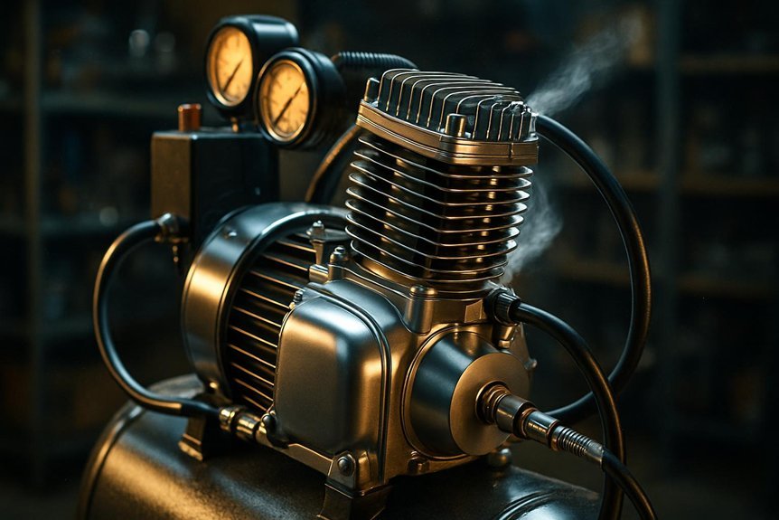
We power the pump by energizing the motor, which converts electrical energy into mechanical rotation that drives the compression stage. The motor transfers torque to the pump via a shaft, coupling, or belt drive, selecting a configuration that balances efficiency and reliability. In direct-drive systems, speed control is tighter, reducing inertial losses, while belt drives allow easy removal for maintenance. We monitor motor current and temperature to infer load and detect inefficiencies before overheating. Mechanical coupling design minimizes misalignment, vibration, and wear, sustaining steady throughput. Dust buildup on cooling fins or drive components degrades thermal performance and can shorten life if unchecked. Noise considerations shape mounting, enclosure, and vibration damping strategies to maintain permissible sound levels during operation.
The Intake Valve and Compression Chamber: What Happens During Compression
The intake valve opens to admit fresh air as the piston moves down, creating a low-pressure region in the compression chamber. We examine how compression proceeds in a controlled, repeatable cycle, focusing on flow, pressure, and timing. Our goal is clarity, not flourish.
- The intake valve opens just as the piston descends, allowing air to enter the compression chamber and begin filling the chamber volume.
- The piston continues down, increasing volume briefly, while the valve then closes to trap the incoming air for compression.
- The piston ascends, raising pressure and temperature, completing the compression cycle and preparing air for delivery.
We monitor valve timing, chamber volume, and pressure rise to ensure efficient, repeatable performance.
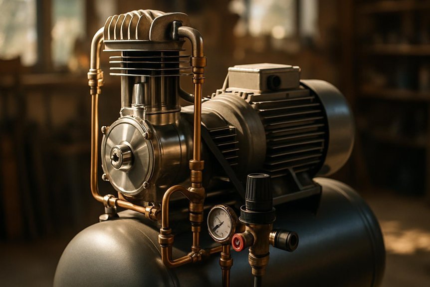
How the Air Is Stored in the Tank and Its Pressure Dynamics
We store compressed air in the tank to provide a ready supply for tools and cycles between compression events. Inside the tank, pressure rises until the cut-in and cut-out settings on the compressor control the cycling, maintaining a usable range. We’ll explore how volume, temperature, and regulator behavior influence storage pressure and immediate delivery performance.
How Tank Stores Air
How does the tank store air and manage pressure once the compressor runs? We explain how storage, volume, and valves interact to hold pressurized air efficiently, while avoiding irrelevant tangent or abstract speculation. Our focus remains precise: containment, pressure limits, and rapid release when demanded.
- Air intake and compression equilibrium: the tank fills to the cut-in pressure, then stabilizes near the cut-out limit to minimize cycling.
- Volume management: larger tanks reduce motor starts; smaller tanks cycle more frequently but deliver faster bursts.
- Safety and regulation: relief valves and gauges monitor pressure, preventing over-pressurization and guiding maintenance decisions.
Pressure Dynamics Inside Tank
An air tank acts as a compressible reservoir where pressure builds as the compressor supplies volume and drops as demand draws air. Inside the tank, we track pressure by considering Boyle’s law-ish behavior for real gases and valve dynamics that regulate flow. The compressor pumps air until the cut-in or target pressure is reached, then it cycles off, maintaining a balance between supply and use. Storage capacity dictates how long tools can run before recharging, while line losses and temperature shifts cause slight pressure fluctuations. Start up challenges arise from motor inertia and moisture release, which can momentarily affect pressure stability. Noise reduction in the system often hinges on improper unloading, regulator choice, and tank isolation. Proper sizing and venting minimize pressure spikes, stabilizing performance across varying loads.
Managing Heat: Cooling and Heat Dissipation in Stationary Systems
We examine heat transfer methods, from conduction to convection, and how they shape pump and motor cooling in stationary systems. We’ll compare cooling system design options and their impact on efficiency, reliability, and maintenance. Our goal is to establish clear thermal management practices that prevent overheat and sustain performance.
Heat Transfer Methods
What mechanisms efficiently remove heat from stationary air compressors, and how do they impact overall performance? We analyze transfer modes that directly affect efficiency, reliability, and duty cycle. Our focus stays on practical methods, not tangents like irrelevant topic or offbeat concept, to keep this discussion precise.
- Conduction and convection through metallic blocks and fins enable rapid heat spreading to coolant paths.
- Fluid cooling via sealed circulating loops transfers heat to radiators or ambient air with minimal pressure loss.
- Phase-change or single-phase liquid cooling, when employed, offers high heat flux with stable outlet temperatures.
These methods influence thermal inertia, compressor longevity, and maintains target discharge pressures, guiding design choices without drifting into unnecessary theory.
Cooling System Design
Efficient cooling system design for stationary compressors centers on delivering heat from the压imate hot zones to a sink with minimal pressure loss and predictable outlet temperatures. We describe a closed loop where coolant absorbs heat, then transfers it to a reservoir or ambient air. Key decisions include pump head, flow rate, and heat exchanger sizing to maintain steady compressor efficiency. We favor direct-contact or plate-fin exchangers to minimize thermal resistance, while minimizing pressure drop across paths. System integrity relies on leak-tight seals, redundant sensors, and robust control algorithms that throttle flow with load. Irrelevant topic and off topic concepts must be avoided to preserve focus.
| Zone | Heat Source | Outlet Temp |
|---|---|---|
| Intake | Ambient air | 40–60°C |
| Motor | Friction | 70–110°C |
| Cylinder | Compression | 90–120°C |
| Aftercooler | Condensing gas | 30–50°C |
Thermal Management Practices
How can we guarantee heat is effectively removed and dissipated in stationary systems without compromising performance? We examine thermal paths, cooling capacity, and control strategies to maintain steady-state temperatures. Effective design disciplines: predict heat flux, select appropriate fans or condensers, and implement robust heat exchangers with low thermal resistance. We avoid irrelevant topic distractions and focus on measurable metrics such as inlet temperature, ambient impact, and duty cycle. A disciplined approach reduces thermal throttling and extends component life, while preserving efficiency. We outline practical steps below to ensure reliability without excess energy use.
- Calibrate cooling load versus duty cycle for steady temperatures
- Choose heat exchangers and airflow paths that minimize resistance
- Implement monitoring and automatic adjustment to prevent hotspots, while avoiding random tangent discussions
Reading Pressure: Gauges, Regulators, and Usable Outlets
Pressure gauges, regulators, and usable outlets form the core interface between the compressor and your tools, so understanding their readings and limits is essential. We read gauges to verify system pressure, monitor fluctuations, and detect deviations from the target setpoint. Regulators adjust downstream pressure, balancing flow demands with safety margins to maintain regulation accuracy. Usable outlets define the actual points of use, where pressure stability governs tool performance and cycle efficiency. We evaluate discharge temperature to anticipate heat-related wear and efficiency loss, aligning cooling and duty cycle decisions. We assess reading gauges against rated ranges, ensuring linear response and minimal hysteresis. In practice, precise control minimizes pressure creep, reduces tool wear, and sustains consistent output for reliable operation and predictable results.
Accessories and Configurations to Boost Performance
We examine how optional tank configurations, regulator variants, and filtration and lubrication options can shape overall performance. By selecting appropriate tank sizes and pressure controls, we optimize delivery consistency and startup reliability while reducing cycling. We’ll discuss how these accessories interact to improve efficiency, maintenance needs, and end-use outcomes.
Optional Tank Configurations
When choosing optional tank configurations, you can boost performance by aligning the tank size and accessories with your typical duty cycle and duty pressure. We assess how larger tanks stabilize pressure and reduce cycling, while compact tanks favor shorter, high-demand intervals. We also consider accessory placement, drain options, and vibration isolation to minimize energy losses. Two word discussion ideas: oil free systems, noise reduction.
- Tank sizing strategy
- Accessory placement and drains
- Vibration isolation and duty alignment
Pressure Regulator Variants
With a stationary compressor, selecting the right pressure regulator variant directly shapes delivery stability and energy use. We evaluate regulator types by pressure setting, droop characteristics, and response time to load changes, ensuring consistent outlet pressure with minimal fluctuation. Different assemblies impact cycle duty and efficiency, so we match bleed, relief, and gauge features to application demands. In practice, a compact integral variant reduces leak paths, while modular options offer easier maintenance. A higher-precision regulator improves control for sensitive tools, yet adds cost and potential friction losses. Irrelevant topic, but necessary to consider how installation geometry affects performance. Random tangent aside, we emphasize compatibility with regulators, hoses, and receivers.
| Type | Key Benefit | Trade-off |
|---|---|---|
| Integral | Compact, fewer leak points | Limited adjustability |
| Modular | Flexible setup | More assembly steps |
| High-precision | Tight control | Higher cost |
Filtration And Lubrication Options
Filtration and lubrication options directly influence air quality, downstream tool life, and overall system efficiency. We approach this topic with practical clarity, outlining how components affect performance and reliability. We focus on how filtration benefits relate to contamination control and downstream results, and how lubrication options impact wear, heat, and maintenance intervals. Our aim is to help you select configurations that balance cost, efficiency, and durability.
- Filtration and separation stages: coalescing, particulate, and moisture control to minimize contaminants.
- Lubrication options: synthetic versus mineral oils, splash versus injected lubrication, viscosity considerations for ambient conditions.
- Monitoring and maintenance: filter change intervals, lubricant analysis, and system diagnostics to sustain optimal performance.
How to Choose the Right Stationary Air Compressor for Your Needs
What key factors should guide your selection of a stationary air compressor? We assess capacity needs, duty cycle, discharge pressure, and outlet pressure consistency to prevent undersizing or overpaying. We balance CFM at your operating pressure with tank size, motor type, and cooling to maintain stable performance under load. Noise, vibration, and footprint matter for stockroom acoustics and workspace integration, so we favor low-RPM, vibration isolation, and compact designs when appropriate. Reliability, maintenance access, and service network influence total cost of ownership, including warranty implications. Energy efficiency, isk factors, and compressor type (reciprocating versus rotary screw) determine long-term operating costs. Finally, we evaluate warranty depth, spare parts availability, and upgrade paths to future-proof the investment while minimizing downtime and unexpected expenses.
Troubleshooting Common Performance Issues and Quick Fixes
From our prior look at selecting the right stationary air compressor, we now address performance issues and quick fixes you can apply on the fly. We’ll stay precise, diagnosing symptoms, not broad generalities, and avoid irrelevant topic detours or off topic idea distractions.
1) Inspect inlet filters and connections for leaks, cleaning or replacing as needed to restore flow and pressure accuracy.
2) Check compressor oil level, venting, and discharge lines; correct partial blockages and reseat fittings to eliminate pressure drop.
3) Verify electrical supply, pressure switch, and safety relief settings; recalibrate or replace faulty components to regain stable duty cycle.
If issues persist, document observations, map fault signs to components, and pursue targeted service rather than vague, irrelevant topic digressions.
Frequently Asked Questions
How Much Noise Does a Stationary Air Compressor Create?
We estimate noise levels at 70–90 dB for typical stationary air compressors, depending on model, duty cycle, and enclosure, with vibration impact mitigated by mounts and isolation; we recommend dampening strategies to minimize transmitted sound and structureborne noise.
What Maintenance Schedule Is Ideal for Long Life?
We recommend regular maintenance intervals every 3–6 months, with lubrication needs tracked and documented; we perform routine oil checks, filter changes, and belt inspections to maximize longevity and minimize downtime, ensuring peak reliability for your compressor system.
Can a Compressor Be Used With Multiple Tools Simultaneously?
Yes, we can power multiple tools simultaneously, but flow and pressure must meet each tool’s demand, so we balance capacity, duty cycle, and regulator settings. two word topic ideas, unrelated subtopic pairs: efficiency vs. vibration. durability vs. accessibility.
What Safety Precautions Are Essential During Operation?
We ensure safe operating procedures by inspecting Hoses, guards, and vents, and maintaining electrical safety, grounding, and proper wiring. We monitor pressure gauges and perform lockout-tagout when servicing, reducing risk during operation and tool changes.
How Do You Determine Annual Energy Costs?
We estimate annual energy costs by multiplying consumption (kWh) by your electricity rate, then compare energy efficiency using cost per unit of output; we compare energy efficiency across models to identify the best long-term savings, reader.
Conclusion
We’ve mapped how stationary air compressors convert electrical energy into stored, usable pressure, from motor-driven compression to tank storage, regulation, and outlets. An interesting stat: a single 5-hp compressor can deliver thousands of cubic feet of air monthly, enough to run heavy tools for extended projects without recharging the system. In practice, understanding intake dynamics, pressure regulation, and cooling helps us optimize duty cycles, reduce wear, and ensure reliable performance across tools and demands.

