We drive air compressor pressure safety through solid foundations, reliable relief devices, and vigilant monitoring. We calibrate gauges, set accurate tool pressures, and ensure vent paths stay unobstructed while mounting securely and torquing correctly. We’ll cover maintenance, fault isolation, and clear tagging to prevent misinterpretation. If you want to prevent missteps and uncontrolled events, you’ll want to consider how these practices interlock with procedures, training, and on-site controls as we proceed.
Key Takeaways
- Implement pressure safety foundations with safeguarded limits, relief devices, and monitoring to prevent equipment damage and operator injury.
- Use proper tagging protocols and communication during service to prevent misinterpretation and verify de-energization and isolation.
- Calibrate and read pressure gauges accurately, verify stability under load, and set tools with controlled regulator adjustments.
- Inspect hoses, fittings, and quick-connects for leaks and wear, replacing damaged components before operation.
- Maintain routine maintenance, reliability checks, and documented tests of pressure controls and emergency shutoffs.
What Makes Air Compressor Pressure Safety Essential
Air compressor pressure safety is essential because uncontrolled pressure can cause equipment damage, operator injury, and system failures. We present safeguards that minimize risk while preserving performance. By enforcing disciplined pressure control, we prevent seal failures, hose ruptures, and component fatigue that threaten reliability. Our approach examines the interplay between pressure limits, relief devices, and monitoring systems, treating each element as a safeguard rather than a standalone measure. We emphasize documented procedures, regular maintenance, and prompt corrective actions to sustain safe operation. In our analysis, we avoid unrelated topic distractions or irrelevant concept digressions, focusing instead on core safety objectives and verification steps. We communicate requirements clearly to the reader, ensuring that responsibilities are understood, response times are defined, and performance remains within approved specifications.
How to Read and Set the Right Pressure for Your Tool
We will examine how to read pressure gauges accurately and translate that reading into the correct tool pressure. By clarifying acceptable ranges and adjusting settings with precision, we assure safe, effective operation. Our discussion covers Reading Pressure Gauges and Setting Tool Pressure as foundational steps.
Reading Pressure Gauges
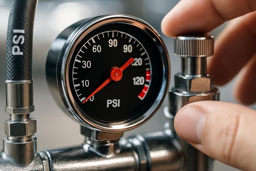
When reading pressure gauges, what exactly should we look for to ensure the tool operates within safe and effective limits? We examine current readings, scale units, and the highest permissible range for the connected accessory. Verify that the display stabilizes quickly and remains within tolerance under load. Check for any drift between repeated measurements, and note fluctuations that exceed manufacturer guidance. Ensure the gauge face is legible, markings are intact, and the needle moves smoothly without sticking. Emphasize proper gauge calibration as a prerequisite for accuracy, and schedule periodic verification against a known standard. Inconsistent readings warrant recalibration or replacement before use. Reading gauges requires disciplined, methodical assessment to prevent overpressure or under-delivery in operation.
Setting Tool Pressure
How can we guarantee tool pressure is set accurately and safely? We begin by defining the required operating pressure for each tool and confirming it against manufacturer specifications. We then adjust regulators with deliberate, incremental changes, observing the gauge response before testing under load. Our approach emphasizes tool calibration to establish a repeatable baseline, ensuring consistent performance across sessions. We also assess hose dynamics, noting pressure losses from fittings, bends, and length, and compensate accordingly to maintain the intended setting at the tool inlet. Precise readings depend on eliminating system leaks and verifying regulator stability during cycling. We document the final setpoint, test intermittently, and revalidate after any service. This disciplined procedure minimizes unexpected pressure fluctuations and enhances overall safety.
Inspecting Hoses, Fittings, and Quick-Connects for Leaks
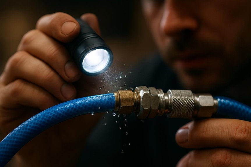
To guarantee safe operation, inspect all hoses, fittings, and quick-connects for leaks before each use. We perform systematic hose inspection and leak detection by examining outer jackets for wear, cracking, and blistering, and by checking fittings for corrosion, looseness, or threading damage. Listen for hissing while applying a light soap solution at joints to reveal microleaks, and ensure that quick-connect couplers engage firmly with proper alignment. Replace damaged components immediately to maintain system integrity and pressure control. Verify that clamps and restraints are intact, and that swivel points rotate smoothly without binding. Any sign of aging, deformation, or pressure increase requires remediation before continued operation.
- Visual hose inspection criteria
- Fitting integrity checks
- Leak detection methods
- Quick-connect condition assessment
How to Install and Verify Safety Relief Valves and Regulators
Ensuring safe operation begins with properly installing and verifying safety relief valves and regulators. We approach installation by confirming compatibility with system pressure, correct orientation, and unobstructed vent paths. We reference manufacturer instructions, mount securely, and torque connections to specification, avoiding over-tightening that could distort seats. After mounting, we perform initial functional checks: apply regulated supply, verify relief setpoints, and observe spring action for prompt response without sticking. Calibration steps include sensor calibration where electronic interlocks or transducers exist, ensuring readings reflect true pressure. We also test for leak-free seals using approved methods. For regulatory compliance, document setpoints and test results. To optimize performance, implement noise reduction strategies in piping and mounting, reducing vibration that could affect valve seating and stability over time.
Best Practices for Hose Management and Placement on Site
We now apply the safety mindset from valve and regulator checks to hose management on site, prioritizing safe placement, proper routing, and clear separation from high-heat or high-vibration areas. Our approach enforces controlled hose routing and disciplined cord management to prevent tripping, snagging, and pressure loss. We specify fixed supports, minimal length slack, and protection from abrasion while maintaining accessibility for inspection and maintenance. We emphasize labeling, color-coding, and documented paths to guarantee consistent operation across teams. Regular scrutiny of connections, couplings, and quick-release mechanisms minimizes downtime and incident risk. Effective hose management reduces energy waste and enhances overall system reliability, aligning with established safety protocols and site standards for continuous uptime.
- hose routing
- cord management
- secure supports and guards
- proactive inspection cadence
Lockout, Tagging, and Operator Safeguards to Prevent Overrun
We implement robust lockout procedures to ensure equipment cannot start during maintenance or faults, preserving system integrity and personnel safety. We require clear tagging compliance to communicate status, authorizations, and residual risks before any work proceeds. We align operator safeguards practices to prevent overrun, emphasizing clear responsibilities, oversight, and site-specific controls.
Lockout Procedures Integrity
Lockout procedures must be executed with unwavering integrity to prevent overrun and ensure personnel safety. We maintain a disciplined framework where lockout, tagging, and operator safeguards are applied consistently, verified by a team-based maintenance mindset and hazard awareness. We insist on clear issuing of permits, durable tags, and standardized sequence checks to prevent misinterpretation or bypass. Our procedures emphasize verification of isolation, energy source control, and residual energy management before any service begins. We document steps, confirm zero-energy conditions, and require authorized personnel to oversee transitions between states. We review deviations, reinforce training, and maintain auditable records to sustain accountability. This integrity reduces exposure risk and reinforces a culture of safety rather than compliance alone.
- Clear isolation verification
- Durable tagging and documentation
- Authorized supervision during transitions
- Regular training and audits
Tagging Compliance Requirements
Tagging compliance is essential to prevent overrun and safeguard personnel during maintenance. We establish tagging and lockout procedures that clearly designate energy sources, sever access to controls, and prevent unintended restart. Our program requires standardized tags with durable, legible identifiers, date stamps, and responsible-party contact information, ensuring immediate verification by authorized personnel. We align tagging practices with risk assessments, detailing material handling steps and circulation routes to minimize exposure during service. Training emphasizes recognizing tag priority, verifying de-energization, and using alternate precautions where tagging alone cannot mitigate residual hazards. We document revocation criteria, perform periodic audits, and maintain records for accountability. We address noise exposure by coordinating tags with equipment status and communication signals, ensuring consistent messaging and preventing misinterpretation during maintenance workflows.
Operator Safeguards Practices
To prevent overrun and protect personnel, operators must apply thorough safeguards—lockout, tagging, and explicit operator controls—before servicing or adjusting air compressor systems. We inspect, verify isolation, and communicate status to all affected personnel, enforcing oversight procedures to ensure consistent application. Our practices reduce accidental energization and protect equipment integrity within warranty limitations, preserving reliable performance. We document steps, monitor interlocks, and confirm zero-pressure conditions prior to any work. We train staff to recognize hazards, maintain records, and adhere to lockout/tagout protocols during maintenance windows. Our safeguards emphasize preventive measures, clear responsibility, and timely communication to sustain safe operations.
- Clear isolation procedures and verification checks
- Precise tagging to indicate status and owner
- Explicit operator controls for restart criteria
- Documentation and incident reporting for continuous improvement
Troubleshooting Common Overpressure and Runaway-Motor Scenarios
What common indicators distinguish overpressure from a runaway motor, and how should we approach these failures to prevent injury and equipment damage? We observe pressure trends, audible cues, and motor speed changes to differentiate causes. Overpressure typically presents with steadily rising downstream pressure, relief valve activation, and heat buildup, while a runaway motor shows uncontrollable RPM increase, loss of proportional control, and rapid temperature rise. In troubleshooting, we verify gauge accuracy, isolate the compressor, and power down using safe lockout procedures if needed. Inspect for stuck relief valves, blocked intake, or control faults. When faults occur, monitor the system for persistent noisy vibration and potential coolant issues, such as degraded cooling or insufficient lubrication, and document root causes for corrective action. Ensure subsequent testing confirms safe restart and restored control.
Routine Maintenance Checklist to Keep Pressure Safety Reliable
Routine maintenance is essential to keep pressure safety reliable, and we implement a structured checklist to prevent faults before they occur. We focus on documenting conditions, calibrations, and critical intervals to sustain optimal performance, energy efficiency, and reliable startup dynamics. Regular inspection of valves, gauges, and safety relief devices ensures accurate readings and timely replacements. We verify oil levels, filters, and lubrication schedules to minimize wear, reduce energy loss, and extend component life. Systematic testing of pressure controls and emergency shutoffs confirms respond-and-reset readiness. Inventory management supports spares availability, minimizing downtime. Our disciplined routine promotes consistent performance, lowers operational risk, and enhances overall safety margins for the compressed-air system.
- Inspect safety relief valves and gauges at defined intervals
- Verify controls, interlocks, and shutdown readiness
- Check filtration, lubrication, and oil condition
- Document findings, calibrations, and maintenance actions
Training and Workplace Rules That Hard-Wire Pressure Safety
Training and workplace rules frame how we apply the maintenance discipline to pressure safety every day. We communicate clear expectations, assign responsibilities, and enforce competencies to prevent errors. Our training emphasizes hazard recognition, lockout procedures, and safe testing practices that align with operational goals. When rules are precise, behavior becomes predictable, reducing risk across shifts and tasks. We avoid irrelevant topic distractions by tying every instruction to compressor operation, energy containment, and PPE usage. Unrelated concept comments are surface-level and not part of daily practice; we focus on documented steps, audits, and corrective actions. To illustrate, consider the table below as a concise reference for essential controls and responsibilities.
| Control / Responsibility | Required Competency |
|---|---|
| Lockout/Tagout | Technician level |
| PPE and guards | All personnel |
| Pressure testing | Authorized personnel |
| Incident reporting | Supervisors |
| Routine audits | Safety team |
Frequently Asked Questions
How Often Should Pressure Relief Valves Be Tested?
Valve testing intervals vary by standard, but we typically test annually. We comply with testing standards and calibration intervals, ensuring functional accuracy. We advise readers that regular verification and documentation are essential for safe operation and regulatory compliance.
What Is the Safe Minimum Work Pressure for Common Tools?
The safe minimum work pressure for common tools depends on tool specs; consult the maintenance schedule and ensure system compatibility. We, however, recommend confirming exact values with the manufacturer to avoid overpressurization or equipment damage.
How Do I Identify a Leaking Regulator Diaphragm?
How do we identify a leaking regulator diaphragm? We identify leaks, diaphragm failure, and misadjustment during troubleshooting and maintenance. Do you see hissing, pressure drop, or fluctuating output as we inspect, test, and verify proper diaphragm integrity and seals?
Can a Clogged Regulator Cause Runaway Motor Risk?
A clogged regulator can contribute to runaway motor risk by causing fluctuating output and insufficient input pressure; we mitigate this through maintenance scheduling, sensor checks, and corrective actions to prevent pressure instability and associated motor overload.
What Audible Warning Signals Indicate Overpressure Conditions?
Audible warning signals indicate overpressure conditions: audible alarms, horn blasts, and sirens, plus pressure-relief valve activity as overpressure indicators. We’ll monitor, verify settings, and respond promptly, ensuring system integrity and operator safety with precise actions.
Conclusion
We safeguard pressure safety by pairing precision with vigilance, yet we’ll never sacrifice performance for procedure. When gauges align with real conditions, misinterpretation fades; when relief valves function, chaos stays at bay. We stay organized and compliant, but we remain ready to act. The calm certainty of routine maintenance contrasts with the sudden risk of neglect. By enforcing tagging and training, we bind safety to operation, ensuring reliability without compromising productivity.

